Stimulation
Module: tutorials.02_EP_tissue.02_stimulation.run
Section author: Gernot Plank <gernot.plank@medunigraz.at>
Extracellular stimulation
Transmembrane voltage can be changed by applying an extracellular field in the extracellular space. As outlined in Sec. Electrical Stimulation, an electric field can be set up either by injection/withdrawal of currents in the extracellular space or by changing the extracellular potential with voltage sources.
For testing the various types of extracellular stimulation we generate a thin strand of tissue of 1 cm length. Electrodes are located at both caps of the strand with an additional auxiliary electrode in the very center of the strand. An illustration of the setup is given in Fig. 62. Extracellular voltage and current stimuli are pre-configured to generate an extracellular voltage drop across the strand of about 2 V. This corresponds to an electric field magnitude of 2 V/cm which is sufficient to initiate action potential propagation under the cathode.
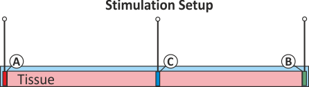
Fig. 62 Simple setup for testing the various configurations for extracellular stimulation. Three electrodes are pre-defined, electrode A and B located at the left hand face and right hand face of the tissue strand, respectively, and an additional auxiliary electrode C sitting on top of the strand in its center.
Experiments
Several types of stimulation setups are predefined. To run these experiments
cd ${TUTORIALS}/02_EP_tissue/02_stimulation
Run
./run.py --help
to see all exposed experimental parameters.
--stimulus {extra_V,extra_V_bal,extra_V_OL,extra_I,extra_I_bal,extra_I_mono}
                      pick stimulus type

--grounded {on,off}   turn on/off use of ground whereever possible
The geometry of the three electrodes A, B and C are defined as follows:
# electrode A
stimulus[0].xd =   100.
stimulus[0].y0 =  -100.
stimulus[0].yd =   200.
stimulus[0].z0 =  -100.
stimulus[0].zd =   200.

# electrode B
stimulus[1].x0 =  4950.
stimulus[1].xd =   100.
stimulus[1].y0 =  -100.
stimulus[1].yd =   200.
stimulus[1].z0 =  -100.
stimulus[1].zd =   200.

# electrode C
stimulus[2].x0 =    -10.
stimulus[2].xd =     20.
stimulus[2].y0 =  -5000.
stimulus[2].yd =  10000.
stimulus[2].z0 =  -5000.
stimulus[2].zd =  10000.
The input parameter stimulus selects a stimulus configuration among the following available options:
Experiment exp01 (extracellular voltage stimulation)
The stimulus option extra_V sets up stimulation
through application of extracellular voltage corresponding to Fig. 43.
The potential electrode A is clamped to 2000 mV for a duration of 2 ms,
electrode B is grounded, i.e.  .
Electrode C is not used here, electrodes A and B are configured as follows:
.
Electrode C is not used here, electrodes A and B are configured as follows:
numstim = 2   # use two electrodes, A and B

# electrode A
stimulus[0].stimtype = 2        # extracellular voltage stimulus
stimulus[0].strength = 2e3      # voltage at A in mV

# electrode B
stimulus[1].stimtype = 3        # extracellular ground
Run this experiment by
./run.py --stimulus extra_V --visualize
Experiment exp02 (balanced extracellular voltage stimulation)
As experiment exp01, the stimulus option extra_V_bal sets up stimulation
through the application of extracellular voltage.
The potential on the left cap is clamped to 1000 mV for a duration of 2 ms
and the right hand electrode to -1000mV. This stimulation circuit corresponds to
the setup shown in Fig. 44.
numstim = 3   # use all three electrodes, A, B and C

# electrode A
stimulus[0].stimtype =  2       # extracellular voltage stimulus
stimulus[0].strength =  1e3     # voltage at A in mV

# electrode B
stimulus[1].stimtype =  2       # extracellular voltage stimulus
stimulus[1].strength = -1e3     # voltage at B in mV

# electrode C
stimulus[2].stimtype =  3       # extracellular ground at C
Run this experiment by
./run.py --stimulus extra_V_bal --visualize
Experiment exp03 (extracellular voltage stimulation with circuit break)
As in experiment exp01, the stimulus option extra_V_OL sets up stimulation
through the application of extracellular voltage.
The extracellular potential at electrode A is clamped to 2000 mV for a duration of 2 ms.
In contrast to the extra_V electrode A is disconnected from the source after stimulus delivery.
Therefore the potental at A is allowed to float after the end of the stimulus,
that is, electrode A won’t act as a ground after delivery of the voltage pulse.
This stimulation circuit corresponds to the setup shown in Fig. 45.
numstim = 2   # use two electrodes, A and B

# electrode A
stimulus[0].stimtype = 5        # extracellular voltage stimulus, switched
stimulus[0].strength = 2e3      # voltage at A in mV

# electrode B
stimulus[1].stimtype = 3        # extracellular ground
Run this experiment by
./run.py --stimulus extra_V_OL --visualize
Experiment exp04 (extracellular current stimulation)
The stimulus option extra_I sets up stimulation
through the application of an extracellular current.
Current is injected into electrode A in the extracellular medium and withdrawn at electrode B,
which is grounded.
The extracellular current strength is chosen to induce an extracellular potential drop of 2000 mV
across the strand as before with extracellular voltage stimulation in extra_V.
This configuration corresponds to the setup shown in Fig. 46.
Electrode C is not used here, electrodes A and B are configured as follows:
numstim = 2   # use two electrodes, A and B

# electrode A
stimulus[0].stimtype = 1        # extracellular current stimulus
stimulus[0].strength = 3.1e6    # current density at A in :math:`\mu A/cm^3`

# electrode B
stimulus[1].stimtype = 3        # extracellular ground
Run this experiment by
./run.py --stimulus extra_I --visualize
Experiment exp05 (balanced extracellular current stimulation)
Similar to experiment exp04, the stimulus option extra_I_bal sets up stimulation
through the injection of extracellular current
with the difference being that B is not grounded. Extracellular current is injected into electrode A
and the same amount is withdrawn from electrode B.
As this constitutes a pure Neumann problem to scenarios can be considered.
Either electrode C is used as a grounding electrode corresponding to Fig. 48,
or we refrain from defining an explicit grounding electrode and use a diffuse ground,
that is, we apply an additional constraint to deal with the Nullspace of the problem.
The latter option corresponds to Fig. 47.
Both configuration also induce an extracellular potential drop of 2000 mV across the strand,
albeit in a symmetric way.
Note that in both cases the compatibility condition must be satisfied.
This is taken care of by CARPentry internally by balancing the total current injected/withdrawn
through electrodes A and B. If balancing is imperfect a stimulation would also occur around electrode C
as all the excess current would drain there.
In the setup with an explicit ground electrodes are defined as:
numstim = 3   # use all three electrodes, A, B and C

# electrode A
stimulus[0].stimtype =  1       # extracellular voltage stimulus
stimulus[0].strength =  3.1e6   # current density at A in :math:`\mu A/cm^3`

# electrode B
stimulus[1].stimtype =  1       # extracellular voltage stimulus
stimulus[1].balance  =  0       # no strength prescribed, balance with stimulus[0]

# electrode C
stimulus[2].stimtype =  3       # extracellular ground at C
To solve the pure Neumann problem without an explicit ground the input parameter grounded is set to on.
In fact, CARPentry turns on this mode automatically if a pure Neumann configuration is detected.
numstim = 2   # use electrodes A and B

# electrode A
stimulus[0].stimtype =  1       # extracellular voltage stimulus
stimulus[0].strength =  3.1e6   # current density at A in :math:`\mu A/cm^3`

# electrode B
stimulus[1].stimtype =  1       # extracellular voltage stimulus
stimulus[1].balance  =  0       # no strength prescribed, balance with stimulus[0]
./run.py --stimulus extra_I_bal --visualize